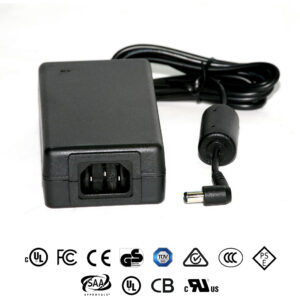
TC 206L CalTrans Power Supply
AC Input, 120W Single DC Output
FEATURES:
- For use in CalTrans 332, 334, and 336 cabinets
- BABAA Compliant Optionally
- For use in Traffic Intersection Control Systems
- For use in LED Road Signs
- High Efficiency / High Reliability
- For use in existing and new configurations
- Custom Configurations Available
- Description
- Specifications
- Data Sheets
Description
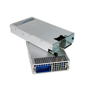
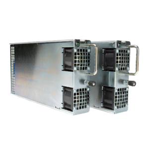
The CalTrans TEES Model 206L Cabinet Power Supply is built to the specifications of the State of California Department of Transportation (CalTrans) Transportation Electrical Equipment Specification (TEES) November 05, 2020. No changes affecting form, fit, function or other features of the module outlined in this document are permitted without prior notification and written approval of CalTrans. TC206L is available as BABAA Compliant optionally.
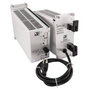
Jasper Electronics TEES Model 206L is a switching power supply capable of delivering up to 120 Watts of DC power through a single, regulated +24V DC output. It provides full output regulation across changes in AC Line voltage and output load over the full operating temperature range of -34°C to +74°C. Power Factor Correction is provided, reducing peak AC Line input current and the associated stress on wiring. This model has a functional AC input range of 80V AC to 270V AC input and 47 to 63Hz.
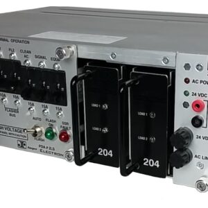
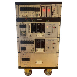
Model 206L is an open frame design, with the main PCB assembly installed in a grounded sheet metal chassis designed to be rack mounted in a TEES type PDA #2L, PDA #3L or PDA #4L assembly as commonly found in 332, 334, or 336 style traffic signal control cabinets. This unit is directly interchangeable with earlier CalTrans Model 206 linear type power supplies, without requiring cabinet modifications.
Please refer to the product Operating Manual for more information.
| INPUT | |
| Voltage/ Current Rating | AC 90-250V, 47-63Hz, 1.6A max, Single Phase |
| TEES Minimum | AC 90-132V, 57-63Hz, 1.6A max |
| Inrush Current | Soft start (~25ºC cold start) 30Apk @ AC 115V |
| Power Factor | >0.98 line PFC typical at AC 115V, full load |
| Efficiency | At AC 115V: >75% @ 1.0A; >84% @ 2.5A; >86% @ 5.0A |
| OUTPUT | |
| Voltage/Current (V/A) | V1 |
| Model CM121-5-M1375G | 24.0V, 5.0A |
| Total loading not to exceed 120 Watts at +165.2°F[+74ºC] | |
| Output Voltage Setpoint | Factory preset within ±2.0% of nominal voltage |
| Line / Load Regulation | <±2.0% at the output connection over the full AC input range and 0 – 100% output loading |
| Minimum Loading | None required |
| Output Turn-on Delay | <200mSec from AC turn-on |
| Over/ Under Shoot | None at turn-on or turn-off |
| Stability | <±0.2% output drift after 20 minute warm-up |
| Temperature Coefficient | <±0.02%/°C, 0° - 50°C, after 20 minute warm-up |
| Dynamic Response | <±5.0% deviation with a 50% load change at a slew rate of 1A/μsec. Output recovers to within 5% in less than 300μsec |
| Ripple and Noise (PARD) | 2.0V max peak-to-peak / 500mV RMS nominal at the output terminal with a 20MHz bandwidth limit. May be measured with a 0.1μF ceramic capacitor in parallel with a 22μF tantalum capacitor connected between the measured output and its return |
| Over Voltage Protection (OVP) | Non-crowbar type from 27.6V to 32.4V |
| Over Current/ Short Circuit Protection | Protected against overload from 6A to 8A and short-circuit faults. Automatic recovery when overload removed |
| Over Temperature Protection | Internal temperature sensing. Causes output to shut down. Automatic recovery |
| Output Transient Protection | Minimum 1400W voltage transient suppressor provided |
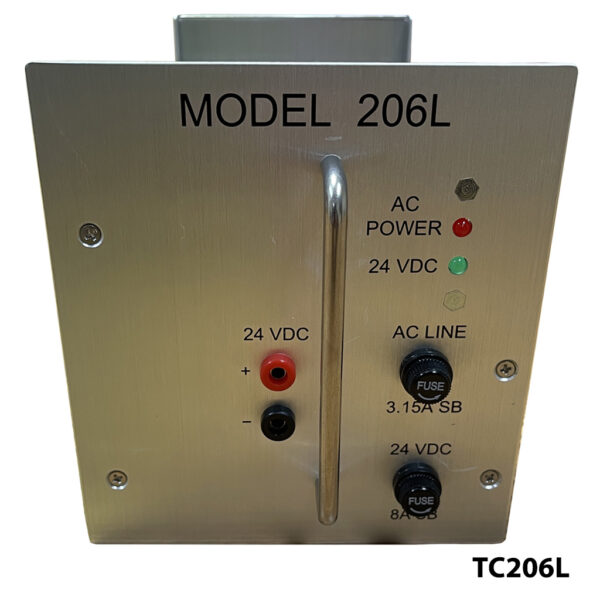
| Output Fusing | AC 8.0A, 250V delayed (slow-blow) action 5x20mm AG cartridge type external fuse provided in the (+) output, operator accessible. Fuse IEC 60127-2/3 compliant |
| SIGNALS, INDICATORS AND CONTROLS | |
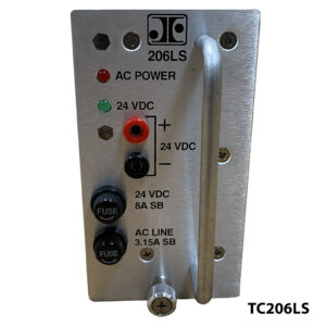
| AC Power Indicator | Front panel mounted, single-color LED. Red indicates AC power ON. Off indicates an input fault |
| DC Power Indicator | Front panel mounted, single-color LED. Green indicates DC power ON. Off indicates an output fault |
| Output Test Points | Two “banana jack” type test sockets provided on the front panel, color coded red and black. Allows operator to verify output voltage |
| MECHANICAL | |
| (Refer to JE Outline Configuration Dwg, P/N 03606-000.) | |
| Mounting Orientation | Designed for horizontal insertion into a TEES specified Power Distribution Assembly (PDA) # 2L, 3L or 4L |
| Weight | 1.36Kg [3.00 lbs] |
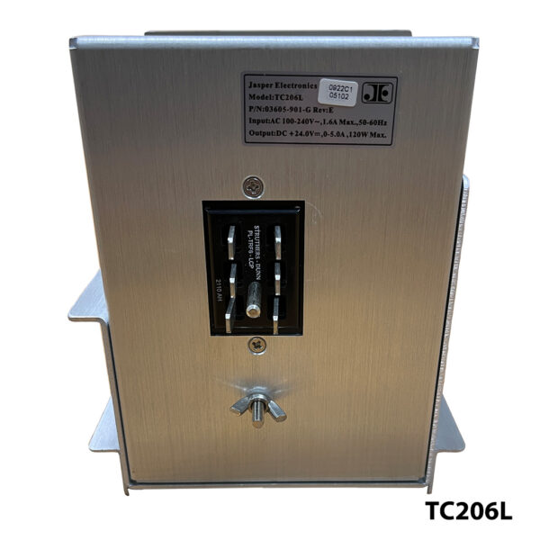
| Retaining Fastener | Operator accessible, 8-32 UNC threaded stud and wing nut provided on the rear panel |
| OPERATING ENVIRONMENT | |
| Operating Temperature | -34.6º – +165.2ºF (-37.0º – +74.0ºC) ambient at full load |
| Cooling | Convection only |
| Relative Humidity | Up to 95% RH, non-condensing |
| Operational Vibration | 0.75G peak, 5 – 500Hz along three orthogonal axis |
| Storage Temperature | -40º to +185ºF (-40º to +85ºC) |
| Altitude | Operating to 10,000 ft. Storage to 30,000 ft. |
| MTBF | Designed for 150,000 hrs at 25°C |
| INTERCONNECT | |
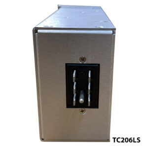
| Input/ Output Connector | 6-circuit (2x3) panel-to-panel plug with 0.250”[6.35mm]x0.055”[1.40mm] blade type contact terminals, rated 15A/pin. General purpose black phenolic insulator material. Secured in the unit rear panel. Cinch model P-2406H-SB. Mates with Cinch model S-2406-SB or equivalent |
| Note: Use of the specified mating connector is required to insure proper current capacity | |
| Pin # | Function |
| 7 | +V1 (+24VDC) Output |
| 8 | DC Ground |
| 9 | Earth Ground |
| 10 | No Connection |
| 11 | N – Neutral (ACC) Input |
| 12 | L – Line (AC) Input |
| Note: Pin number assignments per CalTrans spec TEES 2009, based on the connector manufacturers pin identification method | |
| SAFETY, REGULATORY AND EMC | |
| Designed to comply with the relevant industry standards of the authorities having jurisdiction, typically UL 60950-1, CSA 22.2 and IEC 60950 | |
| EMI Filtering | Meets CISPR22B Level B, EN55022 Level B, and FCC Part 15, Level B, for conducted emissions |
| Immunity | EN 61000-4-2 Level 4, ESD 8kV direct, 15kV air discharge; EN 61000-4-3 Level 3, radiated EMI field; EN 61000-4-4 Level 3, EFT/B; EN 61000-4-5 Level 3, differential / common mode voltage surge; EN 61000-4-6 Level 3, conducted susceptibility |
| Harmonics | Meets EN 61000-3 (harmonics and voltage fluctuations) |
| Touch Current | 1.2mA max @ 50/60Hz, 264V AC per UL 60950 test procedures (Sec. 5.0) |
| Routine Factory Tests | Di-electric strength (hi-pot) to 2121V DC input-to-chassis and input-to-outputs; MegOhm to 500V output-to-chassis |
*Specifications subject to change without notice.

