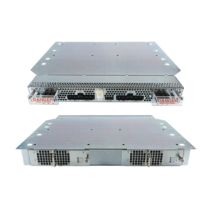
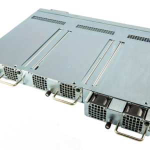
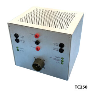
TC 2070-4A CalTrans Power Supply
AC Input, 70 Watt 4 DC Outputs with Standby
FEATURES:
- For use in CalTrans 332, 334, and 336 cabinets
- For use in NEMA TS1 and TS2 cabinets
- BABAA Compliant Optionally
- For use in Traffic Intersection Control Systems
- For use in LED Road Signs
- High Efficiency / High Reliability
- For use in existing and new configurations
- Custom Configurations Available
- Description
- Specifications
- Videos
- Data Sheets
Description
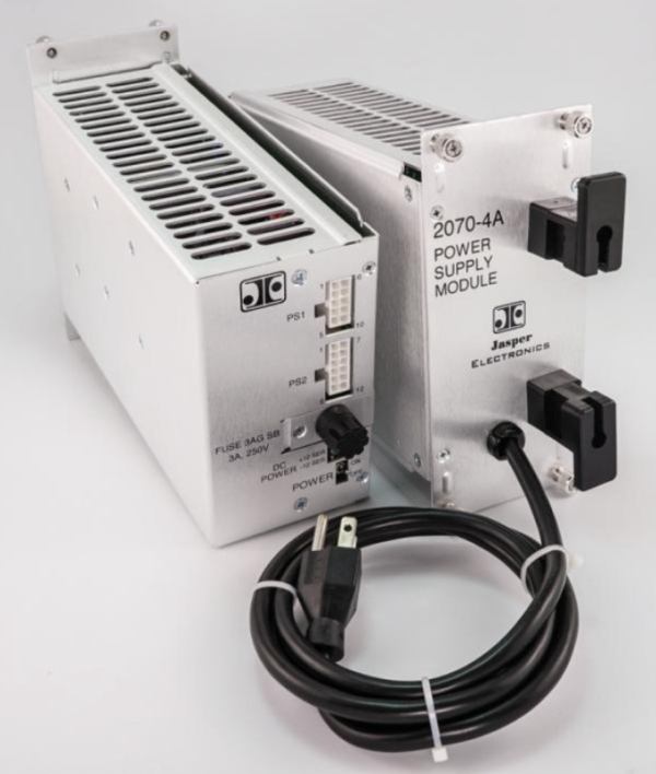
Jasper Electronics (JE) models TC2070-4A+PFC and TC2070-4N(A)PFC component 2070 power supply CalTrans modules are fully compliant to the State of California Department of Transportation (CalTrans) Transportation Electrical Equipment Specification (TEES) dated November 5, 2020 (designated Caltrans models 2070-4A and 2070-4N(A)) for use in Caltrans TEES 332L, 334L and 336L cabinets. Specific design requirements are detailed in the TEES document. The TC-2070-4 Series units are also fully compliant with NYSDOT (New York State Department of Transportation) requirements. These are available as BABAA Compliant optionally.
TC2070-4A, TC2070-4N(A), TC2070-4B, TC2070-4C component non-power factor corrected power supply modules are fully compliant to Cal Trans TEES July 2009 (including Eratta No. 1 January 2010 and Errata No. 2 July 2014.
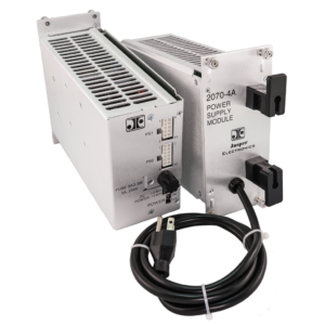
TC2070-4 models are chassis mounted, fully enclosed, 4-output (with standby) switching power supplies capable delivering up to 74 Watts DC. They are designed for non-redundant “cold pluggable” installation in the end product. AC input and PE are via a non-detachable power cord at the rear. DC output power, signal, and control connections are through 1 0-circuit and 12-circuit connectors on the front of the supply. Adjacent on the front panel is a line-side operator accessible input fuse, an On/Off switch, and output condition indicator LEDs. These units are convection cooled, with an extended operating temperature range. They are directly interchangeable with all other CalTrans approved 2070-4 type modules with identical AC input ratings.
Models TC2070-4B and TC2070-4C as shown are user-requested optional configurations. The features and specifications listed may be revised as a result of ongoing development testing and/or additional user requested changes, but as of the user acceptance date of the first article production sample model (Revision Code A,) changes affecting the form, fit, function, or other features outlined herein shall not be permitted without prior notification to and written approval from the user. Please consult the factory for details.
| INPUT | |
| Voltage/ Current Rating | |
| Model TC2070-4A | AC 90-135V, 60Hz±3Hz, 1.6A max. 1Ø Phase Designed to TEES, July 2009 Errata 1 January 2010, Errata 2 July 2014 |
| Model TC2070-4N(A) | AC 90-135V, 60Hz±3Hz, 1.6A max. 1Ø Phase Designed to TEES, July 2009 Errata 1 January 2010, Errata 2 July 2014 |
| Model TC2070-4B | AC 180-264V, 50Hz±3Hz, 0.8A max. 1Ø Phase Designed to TEES, July 2009 Errata 1 January 2010, Errata 2 July 2014 |
| Model TC2070-4C | AC 180-264V, 60Hz±3Hz, 0.8A max. 1Ø Phase Designed to TEES, July 2009 Errata 1 January 2010, Errata 2 July 2014 |
| Model TC2070-4A+PFC | AC 90-135V, 60Hz±3Hz, 1.6A max. 1Ø Phase Designed to TEES, November 5, 2020 |
| Model TC2070-4A+PFC-NYS | Designed to TEES, November 5, 2020 *Standard fuse holder replaced by Shin Chin R3-9C or R3-117B or equivalent |
| Power Factor | > 0.96 typical @ 115VAC, full load Only for TC2070-4A + PFC model |
| Fusing | AC 3.0A, 250V delayed (slow-blow) action 3AG (glass) 0.25”x1.25” cartridge type external line fuse provided, operator accessible |
| Inrush Current | Soft start (~25ºC cold start) 25Apk @ AC 115V |
| Efficiency | At AC 115V: >70% |
| Under Voltage Protection | Auto DC output shutdown when AC input falls below safe operating limits. Automatic recovery when input rises to within normal operating range |
| OUTPUT | |
| Model TC2070-4 | |
| Voltage/Current (V/A) | V1 +5.0V 0.0-10.0A V2 +12.0V 0.0-0.5A (Serial) V3 -12.0V 0.0-0.5A (Serial) V4 +12.0V 0.0-1.0A (ISO) V5 +5.0V 600μA (Standby) V5 is non-operating until AC input failure. |
| Output Voltage Setpoint | Factory preset within ±2.0% of nominal voltage |
| Line Regulation | ±1.0% at the sense point over full AC input range and 0 – 100% output loading, with sense leads connected |
| Load Regulation | <±5.0% at the output connection over the full AC input range and 0 – 100% output loading |
| Remote Sense | V1 output compensates for up to 250mV total line drop in the load cables. Output is internally sensed if leads are opened |
| Minimum Loading | None required |
| Output Turn-on Delay | <1.0 second from AC turn-on |
| Over/ Under Shoot | None at turn-on or turn-off |
| Stability | <±0.2% output drift after 20 minute warm-up |
| Temperature Coefficient | <±0.02%/ºC, 0º - 50ºC, after 20 minute warm-up |
| Dynamic Response | Output recovers to within 1% in less than 500μsec with a 50% load change at a slew rate of 1A/μsec. <±5.0% peak transient deviation |
| Ripple and Noise (PARD) | 50mV max peak-to-peak at the output terminal with a 20 MHz bandwidth limit. May be measured with a 0.1μF ceramic capacitor in parallel with a 22μF tantalum capacitor connected between the measured output and its return |
| Over Voltage Protection (OVP) | Non-crowbar type. Any output exceeding 130%±5% of nominal will cause all outputs to latch off. AC input recycle required to reset |
| Over Current/ Short Circuit Protection | Protected against overload and short-circuit faults. Automatic recovery when overload removed |
| Over Temperature Protection | Internal temperature sensing. Causes output to shut down. Automatic recovery |
| Hold-Up Time | Outputs remain in regulation and capable of supplying 30 watts minimum for 550mSec following AC Fail going LOW. Holds output up for two (2) 500mSec power loss periods occurring within a 1.5 second period |
| Standby Output | Provides power at a minimum constant drain of 600μA from +5 to +2 VDC for 10 hours minimum. Monitor circuitry enables (ON) the +5 VDC Standby output immediately on Power Failure and isolates (OFF) at Power Up |
| SIGNALS, INDICATORS AND CONTROLS | |
| AC On/ Off Switch | Line-side SPST toggle type, vertical throw, rated 5A@120VAC/2A@250VAC on the front panel. Panel silkscreened with function identification and On/Off positions adjacent. “Off” position is “down” |
| DC Power Indicator | 4 front panel mounted, single-color LEDs, one assigned to each output (V1-V4). Green indi-cates DC power ON and output is within ±5% of V-nom. Off indicates an output fault. Panel silk-screened with function and output identification adjacent |
| AC Power, -4A | Fail: Line voltage drops below 92V±2V > 50mS; Restore: Line voltage ≥ 97V±2V > 50mS |
| AC Power, -4N(A) | Fail: Line voltage drops below 85V±2V > 50mS; Restore: Line voltage ≥ 90V±2V > 50mS |
| AC Power, -4B,-4C | Fail: Line voltage drops below 180V±4V > 50mS; Restore: Line voltage ≥ 190V±4V > 50mS |
| AC Power Fail/ Power Down | AC Fail and Power Down output lines go LOW (ground true) immediately upon power failure. The lines transition to HIGH within 50ms after both power restoration and supply are fully recovered. Lines driven separately |
| System Reset/ Power Up | Sysreset and Powerup output lines transition to LOW 525±25ms after AC Fail/Power Down transition to LOW. The Lines transition to HIGH 225±25ms after both Power Restoration and the supply are fully recovered. Lines driven separately |
| Linesync | 60Hz Square Wave Linesync signal is generated by a crystal oscillator which synchronizes to the 60Hz VAC incoming power line at 120 and 300 degrees. A continuous square wave signal is +5 VDC amplitude, and 50±1% duty cycle. The output has a drive sink capability of 16 mA. A 2K Ohm pull-up resistor is connected between the output and +5 VDC. The monitor circuit compensates for missing pulses and line noise during normal operation. Signal disabled when Sysreset transitions LOW and enables when Sysreset transitions HIGH |
| MECHANICAL | |
| (Refer to JE Outline Configuration Dwg, P/N 04185-000-G.) | |
| Mounting Orientation | Designed for horizontal insertion into a TEES specified Model 2070 Controller Unit |
| Weight | 1.59 Kg [3.50 lbs] |
| Retaining Fastener | 4 operator accessible M3x0.5 retractable thumb screw captive fasteners on the rear panel. TEES standard TSD No. 3 |
| OPERATING ENVIRONMENT | |
| Operating Temperature | -34.6º – +165.2ºF (-37.0º – +74.0ºC) ambient at full load |
| Cooling | Convection only |
| Relative Humidity | Up to 95% RH, non-condensing |
| Operational Vibration | 0.75G peak, 5 -500Hz along three orthogonal axis |
| Storage Temperature | -40º to +185ºF (-40º to +85ºC) |
| Altitude | Operating to 10,000 ft. Storage to 30,000 ft. |
| MTBF | Designed for 150,000 hrs at 25°C |
| Maintenance | No routine maintenance is specified or required |
| INTERCONNECT | |
| AC Input, All Models | Non-detachable, 3x16 AWG or 1.5mm2 conductor power cord exits the unit through a strain relief bushing from the rear panel. 2 cord wrap brackets provided adjacent |
| AC Input, -4A | 0.0”±1.0” cord length terminated with a NEMA 5-15P grounding type plug. Rated 13A, 125VA |
| AC Input, -4N(A) | 15.0”±1.0” cord length terminated with a NEMA 5-15P grounding type plug. Rated 13A 125VAC |
| AC Input, -4B, -4C | 40.0”±1.0” cord length terminated with an EU1-16P CEE 7/7 Schuko grounding type plug. Rated 16A 250VAC |
| DC Output/ Signal Connectors | PS1: 10-circuit (2x5) wire-to-board receptacle header with mating locking tab, user accessible through a front panel opening. Rated 9.5A per 0.99”[0.039mm] diameter contact pin, UL 94V-0 rated nylon 66/6 housing material. Tyco/AMP Mini-Universal Mate-N-Lok 2, p/n 1-770971-0. Mates with AMP plug p/n 770580-1 used with user selected AMP socket terminal appropriate for wire gauge and current capacity. PS1 Pin# Function 1 V1 (+5.0VDC) Output. 2 V2 (+12.0VDC) Serial Output. 3 V3 (-12.0VDC) Serial Output. 4 Return, V1,V2,V3 Output (Gnd). 5 V5 (+5.0VDC) Standby Output. 6 (+) V1 Sense. 7 (-) V1 Sense Return. 8 AC Input Power Fail Signal. 9 SYSRESET (System Reset). 10 No Connection. PS2: 12-circuit (2x6) receptacle identical to PS1 above except: Tyco/AMP p/n 1-770972-0. Mates with AMP plug p/n 770581-1. PS2 Pin# Function 1 V1 (+5.0VDC) Output. 2 V2 (+12.0VDC) Serial Output. 3 V3 (-12.0VDC) Serial Output. 4 Return, V1,V2,V3 Output (Gnd). 5 V5 (+5.0VDC) Standby Output. 6 V4 (+12.0VDC) Isolated Output. 7 Return, V4 Output (Gnd). 8 POWERDOWN. 9 POWERUP. 10 EG (Equipment Ground). 11 LINESYNC. 12 No Connection. |
| SAFETY, REGULATORY AND EMC | |
| Designed to comply with the relevant industry standards of the authorities having jurisdiction | |
| Touch Current | 1.2mA max @ 50/60Hz, 115V AC per UL 60950 test procedures (Sec. 5.0) |
| Routine Factory Tests | Di-electric strength (hi-pot) to 2121V DC input-to-chassis and input-to-outputs; MegOhm to 500V output-to-chassis |
*Specifications subject to change without notice.

